How to test, adjust and balance HVAC systems
- Kazi
- Last modified: March 16, 2025
Table of Contents
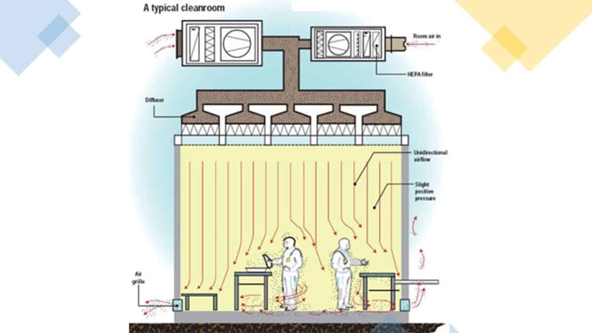
Pharmaceutical manufacturing sites should have procedures and practices for testing, adjusting, and balancing HVAC systems to ensure that installed systems operate in accordance with approved design requirements.
Plant operation and maintenance groups should assume responsibilities to install, test, and adjust when new HVAC systems are installed or when existing HVAC systems are modified in all GMP facilities.
The following guideline outlines the general requirements for total mechanical systems testing, adjusting, and balancing of HVAC systems. Requirements include measuring and establishing the fluid quantities and temperatures of HVAC systems as required to meet design specifications and recording and reporting the results.
This includes, but is not limited to, testing, adjusting, and balancing of the following parts of the HVAC systems:
1. Supply air systems
2. Return air systems
3. General exhaust air systems
4. Local exhaust air systems
5. Hydronic systems
5. Steam humidification systems
6. Temperature control system operation
Why is the testing of HVAC systems necessary?
HVAC systems testing, adjusting, and balancing (TAB) is the process of checking and adjusting all building environmental systems to produce design objectives. It includes:
1. The balancing of air and water distribution
2. Adjustment of the total system to provide design quantities
3. Electrical measurements
4. Temperature measurements
5. Verification of performance of all equipment and automatic controls
6. Sound and vibration measurement
250 SOPs, 197 GMP Manuals, 64 Templates, 30 Training modules, 167 Forms. Additional documents are included each month. All written and updated by GMP experts. Check out sample previews. Access to exclusive content for an affordable fee.
Some useful definitions of HVAC systems maintenance
Before exploring the details of HVAC system testing, let’s examine a few useful definitions of HVAC.
HVAC:
Heating, ventilation, and air conditioning are the use of various technologies to control the temperature, humidity, and purity of the air in an enclosed space. The goal is to provide thermal comfort and acceptable indoor air quality.
Test:
To determine the quantitative performance of equipment.
Adjust:
To regulate the specified fluid flow rate and air patterns at terminal equipment (e.g., reduce fan speed, throttling).
Balance:
To proportion flows within the distribution system (submains, branches, and terminals) according to specified design quantities.
Procedure:
Standardized approach and execution of sequence of work operations to yield reproducible results.
Report forms:
Test data sheets arranged for collecting test data in logical order for submission and review. This data should also form the permanent record to be used as the basis for required future testing, adjusting, and balancing.
Terminal:
The point where the controlled fluid enters or leaves the distribution system or heat transfer occurs. These are supply inlets on water terminals, supply outlets on air terminals, return outlets on water terminals, and exhaust or return inlets on air terminals such as registers, grilles, diffusers, louvers, hoods, and variable or constant volume boxes.
Main, submain, & branchmain:
The main is the duct or pipe containing the system’s major or entire fluid flow.
The submain is the duct or pipe containing part of the system’s capacity and serving two or more branch mains.
The branch main is the duct or pipe serving two or more terminals.
Capture velocity:
The air velocity at a point in space sufficient to draw the contaminated air into the local exhaust hood.
Responsibilities of testing of HVAC systems?
Your company’s Engineering and QA teams are primarily responsible for arranging the testing of HVAC systems.
In many cases, external sub-contractors or agencies specialised in HVAC systems are assigned the job.
1. Quality Assurance and plant engineering teams shall employ the service of an independent testing, adjusting, and balancing (TAB) agency meeting the qualifications specified below as the single source of responsibility for testing, adjusting, and balancing the building mechanical systems to produce the design objectives.
Services shall include checking installations for conformity to design, measuring and establishing the fluid quantities of the mechanical systems as required to meet design specifications, and recording and reporting the results.
2. The independent TAB agency should be certified by the National Balancing Association (s) in those testing and balancing disciplines required for this project and have at least one certified Test and Balance Engineer.
3. The test and Balance Engineer should have at least three years of successful testing, adjusting, and balancing experience on projects with testing and balancing requirements similar to those required for this project.
250 SOPs, 197 GMP Manuals, 64 Templates, 30 Training modules, 167 Forms. Additional documents are included each month. All written and updated by GMP experts. Check out sample previews. Access to exclusive content for an affordable fee.
Codes and standards for testing of HVAC systems?
In the pharmaceutical industry, HVAC systems must be tested to follow the standards and guidelines of the local and international authorities in the field.
Following are some of the agencies and their standards you must follow while testing HVAC systems.
1. ASHRAE:
a) “Practices for measuring, testing and balancing building heating, ventilation, air conditioning and refrigeration systems”, ASHRAE Standard 111.
b) ASHRAE Handbook, Last Edition of HVAC Application Volume, Chapter 34, Testing, Adjusting, and Balancing.
2. National Codes and Standards for Testing, Adjusting, and Balancing of Environmental Systems.
3. SMACNA: HVAC Systems testing, Adjusting and Balancing, Last Edition.
4. NEBB: “Procedural Standards for Testing, Adjusting, and Balancing of Environmental systems”.
5. AABC: “National Standard for Total System Balance”
6. AABC 803 “Site Performance Test Standard – Power Plant and Industrial Fans”.
General rules to follow before testing of HVAC systems?
1. Pre-Balancing Conference
Prior to commencing testing, adjusting, and balancing procedures, the designated business representative should schedule and conduct a conference with the TAB agency, the Architect/Engineer, and representatives of the mechanical system installers.
The objective of the conference is to achieve coordination and verification of system operation and readiness for testing, adjusting, and balancing.
2. Project Conditions
Systems shall be fully operational before starting the procedures. Systems affecting each other must be tested and balanced with all systems’ operations.
3. Sequencing and Scheduling
i. The air systems shall be tested, adjusted, and balanced before hydronic, steam, and refrigerant systems.
ii. Systems affecting each other must be tested and balanced with all systems in operation.
iii. Air conditioning systems should be tested, adjusted and balanced during summer season and heating systems during winter season, including at least a period of operation at outside conditions within 30°C (60°F) wet bulb temperature of maximum summer design condition, and within 5°C (10°F) dry bulb temperature of minimum winter design condition. The final temperature readings should be taken during seasonal operation.
250 SOPs, 197 GMP Manuals, 64 Templates, 30 Training modules, 167 Forms. Additional documents are included each month. All written and updated by GMP experts. Check out sample previews. Access to exclusive content for an affordable fee.
Priliminary procedures for balancing of HVAC systems?
a. Air system balancing
Before operating the system, the TAB agency shall perform the following:
1. Walk the system from the system air handling equipment to terminal units to determine variations of installation from design.
2. Check filters for design specifications and for cleanliness.
3. Check dampers (both volume and fire) for correct and locked positions and temperature control to ensure the completeness of installation before starting fans.
4. Prepare report test sheets for both fans and outlets. Obtain the manufacturer’s outlet factors and recommend testing procedures. Prepare a summation of required outlet volumes to permit a cross-check with required fan volumes.
5. Determine the best main and branch ductwork locations for the most accurate duct traverses.
6. Place outlet dampers in the fully open position.
7. Prepare schematic diagrams of system “as-built” ductwork and piping layouts to facilitate reporting.
8. Check if all motors and bearings are lubricated.
9. Check fan belt tension.
10. Check fan rotation.
b. Hydronic systems balancing
Before operating the system, the TAB agency shall perform the following:
1. Inspect the system completely to ensure that:
(A) It has been flushed out, it is clean, and all air is out of the system;
– All manual valves are open or in operating position;
– All automatic valves are correctly positioned and operative, and the expansion tank is properly charged.
2. Open the valves to the fully open position. Close the coil bypass valves.
3. Check if construction strainer baskets have been replaced with permanent clean baskets.
4. Check pump alignment and rotation.
5. Clean and set automatic fill valves for the required system pressure.
6. Check expansion tanks to ensure that they are not air-bound and that the system is completely full of water.
7. Check air vents at high points of systems and determine if all are installed and operating freely (automatic type) or to bleed air completely (Manual type).
8. Set temperature controls so all coils are calling for full flow.
9. Check the operation of automatic bypass valves.
10. Check and set the operating temperature of chillers to design requirements.
11. Check if all temperature/pressure ports have been installed correctly and are functional.
12. Check if the boiler, chiller, and condenser are started properly.
13. Check if all motors and bearings are lubricated.
250 SOPs, 197 GMP Manuals, 64 Templates, 30 Training modules, 167 Forms. Additional documents are included each month. All written and updated by GMP experts. Check out sample previews. Access to exclusive content for an affordable fee.
How to measure testing, adjusting & balancing of HVAC systems?
a. Measurements
i. The TAB agency should provide all required instrumentation to obtain proper measurements calibrated to the tolerances specified in the referenced standards. The instruments shall be properly maintained and protected against damage.
ii. All provided instruments should meet the requirements of this procedure.
iii. Only instruments with the maximum field measuring accuracy and best sited to the function being measured should be used.
iv. Instruments for airflow measurements must be applied as recommended by the manufacturer.
– Pilot Tube should be used to measure static and velocity pressure in the ductwork to determine the air stream velocity and air quantities in ducts using Digital or Inclined Manometers.
– A rotating Vane Anemometer could measure air quantities at grilles, registers, and velocity across the filter and coil face areas.
– Hot wire Anemometers should be used to measure airflow in local hoods (they may also be used to measure velocity at grilles and registers).
– Use the Flow Hood to proportionally balance the airflow between terminals (branches) for each Branch Main.
b. Measuring instruments
The following instruments should be used for the balancing of the hydronic system:
1. Flow meters (i.e., ultrasonic stations, turbines, venturi, orifice plate, multiported Pilot tubes, and flow indicators).
2. Manometers, ultrasonic digital meters, and differential pressure gauges (either analog or digital).
3. Portable digital meter to measure temperature flow and pressure drop.
4. Portable pyrometers to measure temperature differentials when test wells are not provided.
5. Test pressure taps, pressure gauges, thermometers, and wells.
6. System components used as flow meters (terminal coils, chillers, heat exchangers, or control valves if using the manufacturer’s factory-certified flow versus drop curves).
7. Flow-limiting or regulator devices (to add a variable load to the pump).
8. Pumps with factory-rated flow coefficients Cv, a flow versus handle position and pressure drop table, or a slide rule flow calculator.
Instruments must have a minimum scale, maximum subdivisions, and scale ranges appropriate for the value being measured.
When averaging values, a sufficient quantity of readings should be taken, resulting in a repeatability error of less than 5 percent.
When measuring a single point, readings to be repeated until two consecutive identical values are obtained.
All readings must be taken with the eye at the level of the indicated value to prevent parallax.
Coil testing should be performed with electronic temperature probes. Before starting coil testing, the probes and mercury thermometer should be immersed in a water bath.
All probes should be accurate to within +/- 0.5ºC (1ºF) of the true temperature, and all probes should read within 0.1ºC (0.2ºF) of each when read with the same instrument.
250 SOPs, 197 GMP Manuals, 64 Templates, 30 Training modules, 167 Forms. Additional documents are included each month. All written and updated by GMP experts. Check out sample previews. Access to exclusive content for an affordable fee.
How to perform testing of HVAC systems?
a. Air flow testing, adjusting and balancing procedure
1. Each system identified should be tested and balanced according to the detailed procedures outlined in the reference standards.
2. The location of test measurement (traverse) planes on ductwork and equipment should be determined according to recommendations. Project Management team or plant personnel responsible for reviewing and approving the project should ensure that the consulting team shows the location of the measurement traverses on the duct layout drawings.
3. Measurement planes consist of a series of taps (traverse points) located around the perimeter of the duct or on the vertical sides of a central station air handling unit, packaged air conditioning unit, or plenum. The recommended distance between traverse points for rectangular and round ducts should be provided.
4. Static pressure measurement planes are required at both the fan suction and discharge. Airflow measurement planes can also be located at the fan suction or the discharge.
For dust collection systems, the airflow measurement plane shall be located on the fan suction side or, if space does not permit, on the collector inlet ductwork. When sufficient duct length is not available for a single airflow measurement plane, multiple planes in submains should be used to determine the total fan airflow.
5. If, due to space considerations, the length of straight duct from fan suction and/or discharge to duct elbows (or any other reducing fittings) is below what is recommended, the system effect should be calculated and added to the system total pressure losses.
6. Insulation, ductwork, and piping for installing test probes should be cut to the minimum extent necessary to allow adequate procedure performance.
7. Insulation, ductwork, and housing should be patched by using materials identical to those removed.
8. Ducts and piping shall be sealed and tested for repair leaks.
9. Insulation should be resealed to reestablish the integrity of the vapor barrier.
10. Equipment settings, including damper control positions, valve indicators, fan speed control levers, and similar controls and devices, must be marked to show the final settings. Permanent identification materials should be used.
11. Pilot traverse readings must be reviewed to ensure an acceptable velocity profile at the measuring plane. The uniformity of distribution is acceptable when more than 75% of velocity pressure measurements are greater than 1/10 of the maximum measurement.
12. If the conditions under which the fan operates during a test are different from the fan rating conditions, the field test data should be converted to fan rated speed and inlet air density.
13. The field test valves of the fan motor input must be converted to the same basis as that used in the fan ratings.
14. Minimum data required for establishing the fan’s actual flow rates, conversion to the fan’s rated conditions, and subsequent review of the quality of the overall system balancing should be provided and verified.
15. The variation of actual air flow rates from design criteria should be within the ±10% range for supply, return, and general exhaust systems and within the 0/+10% range for local exhaust systems.
16. The variation of actual fan performance should be within the ± 10% range of the vendor-suggested operation.
17. Reset, adjust, and balance systems subsequent to significant system modifications and resubmit test results.
b. Water systems testing, adjusting, and balancing procedure
1. The water systems should be balanced by direct flow measurement. This allows the pump to be matched to the actual system requirements.
2. Pump suction, discharge, and differential pressure readings should be taken at both full flow and no flow. (For large pumps, a no-flow condition may not be safe—consult the manufacturer.) Based on pressure and power readings, the pump curve should be established to determine the approximate flow rate.
3. Excess pump pressure and operating power should be eliminated by trimming the pump impeller or reducing the pump speed. The use of throttle valves to absorb the excessive pressure adds a lifelong operating cost penalty to the system’s operation and is, therefore, not allowed.
4. The variation of actual water flow from the design criteria should be within ±10% range; however, the ±5% tolerance band should be used for chilled water supplied to coils when high latent capacity is required and for heating terminals using low-temperature water.
5. The proportional balancing method using direct measurement flow meters should be preferred. The ratio between actual measured and design water flows should be determined and applied to all terminals.
Manual balancing valves must be adjusted to balance the system proportionally. The balancing should be accomplished in a logical sequence from the coil (branch, riser, and header) with the lowest percent of design flow to the one with the highest percent of design.
6. The pressure drop across the balancing valve at the pump discharge is the pressure produced by the pump that is not required to provide the design flow rate to the system.
Once the excess pressure is removed as described above in item 2, the pump discharge balancing valve must be reopened to its wide-open position.
7. When the system uses three-way valves, the balancer should set the coils for full flow and balance on full flow through the coil. Then, change the three-way valve to full bypass and set the bypass balancing valve.
If the system uses two-way valves with a bypass loop at the end of the system or at the pump, the balancer should set the system to full flow and balance with the bypass closed.
Then, the differential pressure between the supply and return mains should be measured, and the bypass balancing valve should be set to maintain the differential pressure.
8. When a system with a primary and secondary loop is used, the primary loop should be balanced first. The system must be balanced for full flow in both the primary and the secondary loop.
9. After the system is balanced, the balancing valve should be fully open at least on one branch.
250 SOPs, 197 GMP Manuals, 64 Templates, 30 Training modules, 167 Forms. Additional documents are included each month. All written and updated by GMP experts. Check out sample previews. Access to exclusive content for an affordable fee.
c. Steam systems testing, adjusting, and balancing procedure
1. Steam distribution systems should be balanced by ensuring that the pressure drops are equalized at design flow rates for all portions of the piping system.
2. The spring-type pack-less supply valves equipped with pre-calibrated orifices or orifice flanges could regulate and measure steam flow at appropriate locations throughout the system.
3. The orifice sizes are determined by the pressure drop required to provide a given flow rate at a given location in the system. A schedule should be prepared showing
– Orifice sizes
– Valve or pipe sizes
– Required flow rates, and
– Corresponding pressure differentials for each flow rate
4. After the appropriate regulating orifices are installed in the proper locations, the system should be tested for tightness by sealing all openings and applying a vacuum of 70 kPa (20 in.Hg), held for 2 hours.
d. Coils capacity testing, adjusting and balancing procedure
1. Each cooling and heating coil, including reheat coils, should be tested for total performance. All coils shall be tested with the design air and water flowing through them. The test shall not be performed at less than 90 to 95% of the design load.
2. The entering and leaving air temperatures and the entering and leaving water temperatures shall be simultaneously recorded.
3. At least six temperature probes should be used for testing chilled water coils:
– Entering air dry-bulb temperature;
– Entering air wet-bulb temperature;
– Leaving air dry-bulb temperature;
– Leaving air wet-bulb temperature;
– Etering chilled water;
– Leaving chilled water.
4. A hot water heating coil test requires at least four temperature probes:
– Entering air dry-bulb temperature;
– Leaving air dry-bulb temperature;
– Entering hot water;
– Leaving hot water.
5. Steam and DX coils require measuring the entering and leaving air temperature. (The entering steam pressure should also be recorded for steam coils.)
6. The test results should be converted to specified conditions to compare with the specified coil capacity.
7. Use appropriate forms to report coil performance test.
e. Records and report data on HVAC systems testing
1. All data obtained during testing, adjusting, and balancing should be recorded in accordance with forms recommended by the referenced standards and as approved on the sample report forms.
2. The TAB agency shall prepare a report with recommendations for correcting unsatisfactory mechanical performance when the system cannot be successfully balanced.
3. Based on the balancing report, Plant Engineering should finalize the forms and attach them to the TAB report and installation operation and validation protocol.
f. Training on HVAC systems testing
The testing and balancing Engineer shall train the company maintenance personnel on troubleshooting procedures and testing, adjusting, and balancing procedures. The engineer shall also review with personnel the information contained in the operating and maintenance Data.
The training schedule should be made with the company through the Architect/Engineer at least 7 days prior to commencing testing.
Conclusion
To properly test, adjust, and balance HVAC systems in pharmaceutical environments, start by ensuring all design specifications are clearly understood and documented.
Engage qualified professionals to perform systematic checks, focusing on airflow, pressure, temperature, and humidity control. Make necessary adjustments to meet specified performance criteria and re-test to confirm consistency.
The testing process for HVAC systems involves verifying that airflow rates, room pressures, temperatures, and humidity levels meet design and regulatory requirements.
Instruments measure these parameters at various points, ensuring even distribution and correct functioning. Adjustments are made where needed, followed by retesting to confirm stability.
Detailed records are kept throughout to demonstrate compliance and performance consistency.
Coordination between engineering, validation, and quality teams is crucial throughout the process. This approach should ensure the compliance and efficiency of HVAC operations while protecting product quality and personnel safety.

Author: Kazi Hasan
Kazi is a seasoned pharmaceutical industry professional with over 20 years of experience specializing in production operations, quality management, and process validation.
Kazi has worked with several global pharmaceutical companies to streamline production processes, ensure product quality, and validate operations complying with international regulatory standards and best practices.
Kazi holds several pharmaceutical industry certifications including post-graduate degrees in Engineering Management and Business Administration.